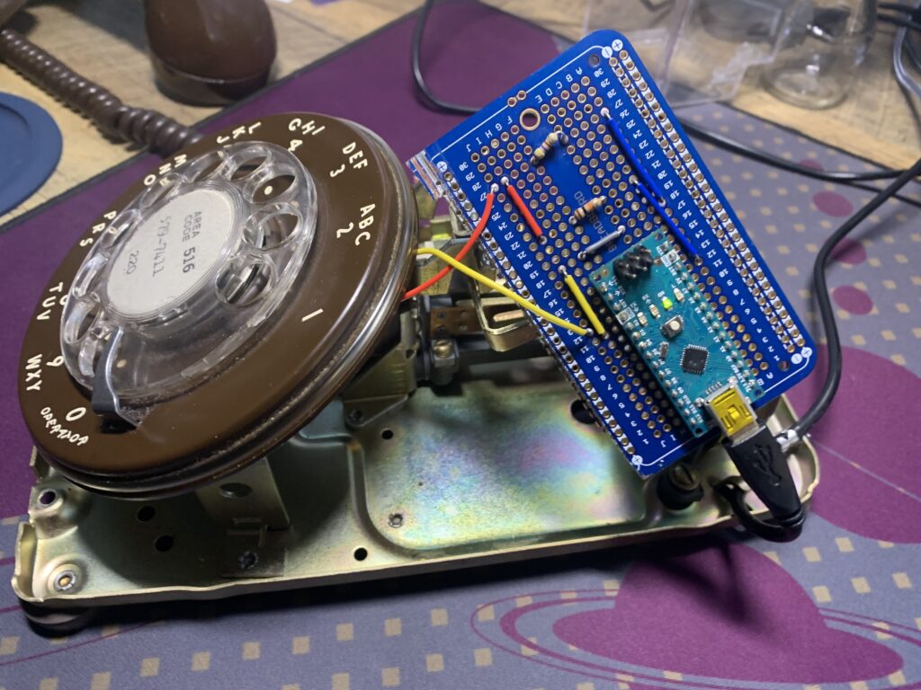
With my research phase complete, I had a clear understanding of components to buy and how they’d go together. Huge thanks to CameronCoward for his instructables post: https://www.instructables.com/Vintage-Rotary-Phone-Dial-PC-Volume-Control/
It’s a rather simple system:
- As the rotary dial spins, it will open and close a circuit.
- This opening and closing changes the voltage of a circuit.
- The Arduino Nano interprets the change in voltage (high/low) to count the “clicks” of the rotary dial and send a number over to the serial port.
- A python script on the computer will listen to this serial port, accepting the numbers and doing something with them.
The hardest part for me was removing the dial. A number of screws had rusted. A little WD-40 helped. In one case, the screw head was stripped and I had to use a hacksaw to cut a new slot for the screw driver.
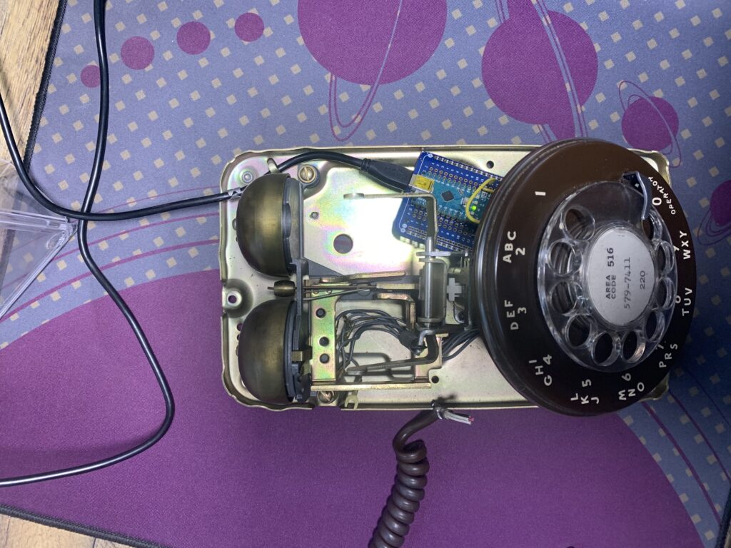
Once everything was apart, I also removed components I didn’t need. There was a plastic box that everything wired into. Removing that created plenty of room for the breadboard circuit.

If you are interested in building this for yourself, I highly suggest you read through Cameron’s post as well as Guidomax’s instructables: https://www.instructables.com/Interface-a-rotary-phone-dial-to-an-Arduino/
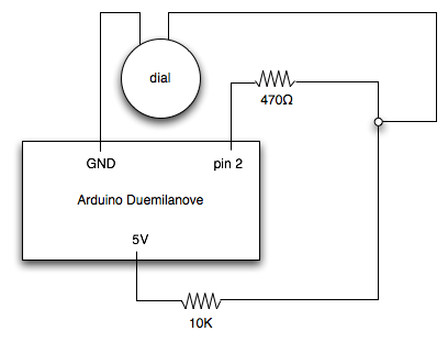
Below is the circuit diagram from Guidomax:

